Free-Body Diagrams⁚ A Comprehensive Guide
This guide provides a comprehensive overview of free-body diagrams, essential tools for solving mechanics problems. Learn to draw accurate diagrams, identify forces (gravity, tension, friction), and apply Newton’s laws to determine unknowns. Master equilibrium conditions and advanced applications, including complex systems and rotational motion. Resources for further learning are also included.
What is a Free-Body Diagram?
A free-body diagram (FBD) is a simplified visual representation of a physical object, isolated from its surroundings, showing all the forces acting upon it. These forces are depicted as vectors, arrows indicating both magnitude and direction. The size of the arrow often represents the relative strength of the force. FBDs are crucial for understanding and solving problems in statics and dynamics. They help visualize the interaction between an object and its environment. By isolating the object, we focus solely on the forces influencing its motion or equilibrium. The process of creating an FBD involves identifying all external forces—gravity, normal forces, friction, tension, applied forces, etc.—and representing them accurately on the diagram. This systematic approach simplifies complex problems, making them easier to analyze and solve using Newton’s laws of motion or equilibrium equations. A well-drawn FBD is neat, clear, and includes all necessary information for solving the problem. It’s a fundamental tool in physics and engineering, used to predict an object’s behavior under various force conditions.
Drawing Free-Body Diagrams⁚ A Step-by-Step Approach
Constructing a free-body diagram (FBD) involves a methodical approach. Begin by isolating the object of interest, mentally separating it from its surroundings. Represent the object with a simple shape—a box, circle, or whatever best suits its form. Next, identify all forces acting on the isolated object. These include gravitational force (weight), acting downwards; normal forces, perpendicular to contact surfaces; frictional forces, opposing motion; tension forces, along ropes or cables; and applied forces, such as pushes or pulls. Represent each force with a vector arrow, originating from the object’s center of mass. The arrow’s length should roughly reflect the force’s magnitude, while its direction precisely indicates the force’s action. Clearly label each force with its appropriate symbol (e.g., W for weight, FN for normal force, Ff for friction). Choose a suitable coordinate system (typically x-y or x-y-z axes) to help resolve forces into components, simplifying calculations. Finally, review your diagram to ensure all forces are included and accurately represented. A well-executed FBD lays the foundation for effectively solving problems involving forces and motion.
Types of Forces in Free-Body Diagrams
Free-body diagrams (FBDs) incorporate various force types. Gravitational force (weight), denoted by ‘W’ or ‘mg’ (mass times gravitational acceleration), always acts vertically downwards; Normal force (FN), a reaction force from a surface, acts perpendicular to the contact surface, preventing penetration. Frictional force (Ff), opposing relative motion between surfaces, acts parallel to the contact surface. Tension force (T), transmitted through a rope, cable, or string, acts along the direction of the rope or cable, pulling on the object. Applied forces (Fapp) represent external pushes or pulls on the object, acting in the direction of the applied force. Spring force (Fs), exerted by a compressed or stretched spring, is proportional to the spring’s displacement from its equilibrium position (Hooke’s Law). These forces, represented by vectors on the FBD, provide a complete picture of the forces acting upon the object, enabling the application of Newton’s laws to determine its motion or equilibrium state. Accurate identification of these forces is crucial for the correct solution of mechanics problems.
Common Examples of Free-Body Diagrams
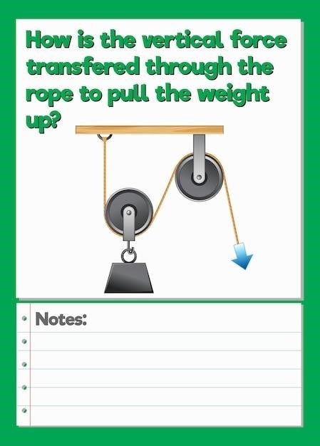
Numerous scenarios benefit from free-body diagrams. Consider a block resting on an inclined plane. The FBD shows the weight acting vertically downwards, the normal force perpendicular to the plane, and friction parallel to the plane, opposing motion. A simple pendulum involves the weight of the bob acting vertically downwards and the tension in the string acting along the string towards the support point. Analyzing a spring-mass system requires depicting the weight of the mass, the spring force acting upwards (if the spring is stretched), and any external forces. For a car accelerating, forces include the forward thrust from the engine, air resistance acting opposite to motion, and friction from the road. A pulley system with multiple masses would show tension forces in the rope segments, the weight of each mass, and any normal or friction forces at contact points. Each example emphasizes the importance of accurately representing all forces acting on each object within the system to properly analyze its behavior.

Solving Problems with Free-Body Diagrams
Free-body diagrams are crucial for applying Newton’s laws to solve mechanics problems. By analyzing forces, we determine unknown quantities like acceleration, tension, or friction. Equilibrium conditions provide additional insights into static scenarios.
Applying Newton’s Second Law
Newton’s second law, ΣF = ma, is the cornerstone of solving dynamics problems using free-body diagrams. The law states that the net force acting on an object is equal to the product of its mass and acceleration. To apply this law effectively, carefully construct a free-body diagram showing all forces acting on the object of interest. Remember to resolve forces into their components along a chosen coordinate system. This simplifies the vector addition of forces and allows for easy calculation of the net force in each direction. Once the net force is determined, applying Newton’s second law directly yields the object’s acceleration. This approach is particularly useful for analyzing the motion of objects under the influence of gravity, friction, or applied forces. Solving for acceleration allows the determination of an object’s velocity and position as a function of time. For systems with multiple objects, create separate free-body diagrams for each object and apply Newton’s second law to each. The resulting equations, when solved simultaneously, will reveal the motion of the entire system.
Solving for Unknowns
After constructing a free-body diagram and applying Newton’s laws, the next step involves solving for unknown quantities. This often involves solving a system of equations, with each equation representing a component of Newton’s second law (or equilibrium conditions for statics problems). The number of equations needed will match the number of unknowns. These unknowns might include forces, accelerations, or angles. Techniques such as substitution, elimination, or matrix methods can be employed to solve the system of equations. Careful attention to units is crucial throughout the calculation process. Once the system of equations is solved, check the solution’s reasonableness. Do the results match your intuition about the problem? Are the magnitudes and directions of the forces plausible? For example, a calculated tension force should not be negative, as tension is always a pulling force. If inconsistencies arise, re-examine the free-body diagram and equations for potential errors. Remember that properly drawn diagrams and clearly written equations are essential for successfully identifying and solving for unknowns.
Equilibrium Conditions
Equilibrium conditions are fundamental when analyzing free-body diagrams depicting systems at rest or moving with constant velocity. For a system to be in translational equilibrium, the net force acting on it must be zero. This implies that the vector sum of all forces in each direction (typically x and y) equals zero. Mathematically, this is represented as ΣFx = 0 and ΣFy = 0. In rotational equilibrium, the net torque acting on the system must also be zero. Torque, a measure of rotational force, depends on the force’s magnitude, its distance from the pivot point (axis of rotation), and the angle between the force and the lever arm. The equilibrium condition for rotational equilibrium is Στ = 0. These conditions are crucial for solving statics problems, where the focus is on systems at rest. Analyzing these conditions allows the determination of unknown forces or reactions within a system. For example, determining the support reactions on a bridge or the tension in cables supporting a weight. Remember, satisfying both translational and rotational equilibrium conditions ensures the overall stability of a system.

Advanced Applications of Free-Body Diagrams
This section explores complex scenarios, encompassing systems with multiple interconnected objects and the incorporation of rotational motion. Limitations of free-body diagrams and further learning resources are also addressed.
Free-Body Diagrams in Complex Systems
Analyzing complex systems using free-body diagrams requires a systematic approach. Begin by isolating each object within the system, creating a separate free-body diagram for each. Carefully identify all forces acting on each object, including internal forces between connected objects. Remember that Newton’s Third Law dictates that internal forces occur in equal and opposite pairs. For example, consider a system of connected blocks on an inclined plane. Each block will have its own weight acting downwards, a normal force from the surface, and possibly friction. Additionally, there will be tension forces between the blocks, acting in opposite directions on each.
Solving such problems often involves setting up a system of simultaneous equations, one for each object, based on Newton’s Second Law (ΣF = ma). Solving these equations simultaneously allows determination of accelerations and internal forces within the system. The key is to meticulously account for all forces acting on each isolated object and to apply Newton’s Laws correctly. Practice with various complex scenarios will build proficiency in this crucial aspect of mechanics.
Free-Body Diagrams and Rotational Motion
Extending free-body diagrams to encompass rotational motion involves considering torques. A torque, or moment, is a rotational force produced by a force acting at a distance from the axis of rotation. The magnitude of a torque is calculated as the product of the force’s magnitude and the perpendicular distance from the force’s line of action to the axis of rotation. When drawing free-body diagrams for rotational motion, indicate the location of the axis of rotation. Forces acting at a distance from this axis will generate torques. The direction of the torque is determined by the right-hand rule⁚ if you curl your fingers in the direction of rotation caused by the force, your thumb points in the direction of the torque vector.
For equilibrium in rotational motion, the net torque about any axis must be zero (Στ = 0). This condition, in addition to the translational equilibrium condition (ΣF = 0), allows for the solution of problems involving both linear and rotational motion. For objects undergoing rotational acceleration, the net torque is equal to the moment of inertia times the angular acceleration (Στ = Iα). Free-body diagrams, incorporating both forces and torques, provide a powerful tool for analyzing a wide range of scenarios, from simple levers to complex rotating machinery.
Limitations of Free-Body Diagrams
While invaluable for simplifying complex systems, free-body diagrams possess inherent limitations. They are inherently simplified representations; they neglect the internal forces within an object, focusing solely on external interactions. This simplification is valid for rigid bodies but fails for deformable objects where internal stresses significantly affect behavior. The assumption of point masses or rigid bodies also overlooks the object’s size and shape. While useful for many situations, this simplification breaks down when dealing with distributed forces or complex geometries where the force application point significantly impacts the resulting motion or stress distribution.
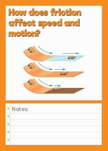
Free-body diagrams rely on idealized models; friction is often represented by a single force, neglecting its complex dependence on surface properties and relative motion. Similarly, air resistance is frequently ignored, which is reasonable for low-speed scenarios but inaccurate at higher velocities. The accuracy of a free-body diagram’s predictions hinges on the validity of these idealizations. It’s crucial to carefully consider the limitations of these assumptions when interpreting results and ensuring the model reasonably reflects the real-world scenario. Advanced techniques, such as finite element analysis, may be necessary for scenarios where these limitations become significant.
Resources for Further Learning
Numerous resources are available to enhance your understanding of free-body diagrams. Many introductory physics textbooks dedicate chapters to this topic, providing detailed explanations, worked examples, and practice problems. These texts often include visual aids and step-by-step solutions to reinforce learning. Online platforms, such as Khan Academy and MIT OpenCourseware, offer free video lectures and interactive exercises covering free-body diagrams and related concepts in mechanics. These online resources provide flexibility and cater to diverse learning styles. Furthermore, dedicated websites and forums offer additional practice problems, solutions, and discussions facilitated by experienced instructors or fellow students. These platforms offer valuable support for overcoming challenges and clarifying any misconceptions.
For a more advanced approach, consider exploring engineering mechanics textbooks. These resources delve into more complex applications, incorporating concepts like stress, strain, and deformation. They often include detailed examples from structural engineering, mechanical design, and other relevant fields. Remember to search for “free-body diagram tutorials,” “free-body diagram examples,” and “free-body diagram practice problems” online to locate numerous additional resources. By utilizing a combination of these resources—textbooks, online platforms, and dedicated websites—you can comprehensively enhance your understanding and proficiency in drawing and interpreting free-body diagrams.
